Short stories for some of my personal hardware projects.
-

Signal Tracer
A simple, very high gain signal tracer. It was designed to be low noise and low power consumption. It is fitted with contact and contactless probes, low and high pass filters, a 2W speaker and extension headers to interface with other measuring devices, such as osciloscopes and spectrum analyzers. It can be used with both H-field and E-field contacless probes. The picture shows the preamplifier stage, but the full device is composed of 3 main modules: The probe — that can be active or passive — the preamplifier, and the power amplifier that connects to the speaker.
-

Network Analyzer
I designed and built this gadget when I was restructuring and upgrading my network and cabling infrastructure in my lab. It helped me a big deal as a small, battery operated, portable analyzer for routine testing, debugging and setup. Someday I might make a blog post about its design, firmware and construction. It’s not just a cable tester, it’s a full featured network analyzer, connectivity tester and bandwidth tester - an all-in-one sort of thing.
-
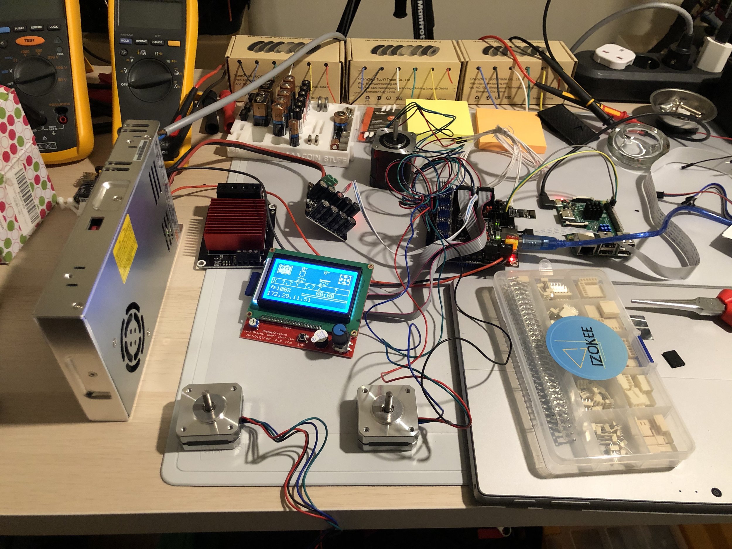
3D Printer Overhauling
Essentially, all the original electronics from my CR-10s were removed and replaced by an SKR board, improved Trinamic drivers, better bed MOSFETs, integrated UPS and auto shutdown relays, a very welcome BLtouch, and a completly redesigned head with multi extruder, multi hotend support. The Marlin firmware configuration took a considerable amount of time to get right, but well worth the effort. I also included an RPi with an UART connection to the SKR board, where I installed OctoPrint that can be accessed wirelessly.
-

Capacitor Leakage Tester
Although it was designed to be a simple capacitor leakage tester, but it can actually be used as a more generic resistance comparator. The ZIF socket accepts two components — a known resistance in the M/GOhm range, and the DUT. The output header is connected to a buffer stage, and then it can be interfaced with an ADC or just a couple of leds through a comparator to indicate a good/bad status. This device is rarely needed around here, but when I need it, I’m glad I made it.
-

High-Voltage Variable PSU
This PSU can supply 200W of power and provides a regulated output from 30 VDC to 400 VDC. The input must be already rectified, which in my case I use another device I built to do the job (see HV Rectifier). I mainly use this PSU for tube amp projects. It has two independent channels, and I don’t recommend anyone building something like this unless you have good protection gear and you know the risks involved.
-

High-Voltage Rectifier
It is essentially a high voltage bridge rectifier, a few diodes for reverse protection, and two very big electrolytic capacitors inside. I use this to interconnect a Variac to my High-Voltage PSU, as it requires rectified input. It is designed to accept a maximum input voltage of 425 VAC and a maximum output voltage of 600 VDC. Sometimes it also serves as a capacitor reforming device when HV caps worth the effort.
-

Modular 10-ch PSU
Some time back I needed a considerable amount of power supply channels for debugging purposes on an equipment I was working on. I could do it with a few regulators on a breadboard, or I could just build a modular power supply from scratch… I went with the latter. The picture shows the main board. It’s designed to plug-in custom, easy-to-build modules on top of it through the female headers. It supports up to 5 modules, 2-ch each, totalling 10 channel support.
-

Atomic Clock
I always wanted to have an atomic clock. The day I could score a rubidium frequency standard, at a very decent price on eBay, was cheerfully celebrated. I picked up a chassis I had around, a ready-to-use switched power supply, a few leds, resistors and transitors, designed and printed a custom front-panel - and there it is… Although I don’t use it as much as I thought I would, it still is an handy piece of equipment to have around when I effectively need it.
-

RF Power Meter
An RF Power Meter is a life saver, specially if the life of your testing gear depends on it. I built this power meter based on a cheaply designed evaluation board for the AD8317 I bought from eBay. Curiously — but not unheard of, given the cost per unit — the evaluation board was delivering incorrect readings when it arrived. I narrowed it down to a few design flaws: the input resistor was missing a connection to ground, the input capacitors were of the wrong value according to AD specs, as well as an output resistor that was offspec. I also removed an inductor that was present on the supply rail for some reason, and added another bypass cap. After that, I plugged it into an Arduino, LCD and Serial-USB converter, and I’ve been using it ever since. The firmware I wrote is fairly simple, as the AD8317 analog output is simple enough to deal with — it just requires a simple calibration procedure within the Arduino firmware to obtain accurate enough results.
-

RF Power Reference
This is a well-known, easy to build RF Power Reference. It was originally designed by HP if I’m not mistaken, and there are a considerable amount of online resources with multiple variations of the original design. It is an extremelly simple design, using an oscilator to generate the initial signal, then it’s clipped by two diodes, filtered to remove HF content, and attenuated to obtain the desired output power level. I built this with a slight modification to provide configurable power outputs. The default (and original) output power is -10dBm. I use it to calibrate my RF Power Meter.
-

Flipper w/ RPi Pico
I built this simple devboard to experiment with Flipper firmware development, taking advantage of a RPi Pico to have access to ready-to-use ADC’s and use it as an interface to other hardware. I haven’t done much on this project since then, but it was extremelly useful to better understand how the Flipper firmware was designed and how to develop custom applications for it.
-

PCB w/ CNC
Not exactly a gadget, but this was a process that took me some time to get right. I started wondering if I could use my small scale CNC to produce PCBs with proper track width accuracy, but preliminary tests revealed that my small CNC wasn’t good enough for the job. I decided to upgrade a few parts, made a few modifications in the chassis, installed a decent 500W spindle (included a new power supply to feed the new spindle) and the results become a lot better. After many hours of experiments with the Gerber files, CNC software configuration, firmware debugging, and a considerable amount of different router bits of the most variable shapes and angles, I ended up with a process that gives me good enough results for home PCB production, with dual-layer support, and accurate enough for SOIC pads - that’s all I needed. Ironically, I still make most of my prototypes in pre-drilled PCBs, unless there’s a specific need to go with the CNC way.